
Table of Contents
Simple MODBUS MCU Source Code and Explanation
Download MCU Source Code
- This source code is an ANSI C implementation for an STM32 MCU.
- This source code was tested on a board made by COMFILE Technology. It may need to be adapted to work on other boards.
- This program is distributed in the hope that it will be useful, but without any warranty; without even the implied warranty of merchantability or fitness for a particular purpose.
- COMFILE Technology does not provide technical support for this source code.
Why Use Simple MODBUS
Because Simple MODBUS is a simpler subset of standard MODBUS RTU, it is easier to implement and has a smaller code footprint. Because Simple MODBUS is supported by the ComfileHMI, it makes it easier to add an HMI to any MCU-based application.
This implementation may not respond to some queries if it is interfaced with 3rd party HMI software that implement the complete Modbus RTU standard.
MCU Selection
The following features are required to use the Simple MODBUS MCU implementation.
- MCU must have a UART that supports a receive interrupt.
- MCU must have a timer that can tick every 1mS.
Recommend MCUs include ARM Cortex-M, PIC18, or AVR Mega.
Memory Allocation
Coil and Register memory should be declared as global static arrays.
static unsigned char MDcoil[100];       // Each char is 8 bytes, so this is enough space for 800 bits
static unsigned short MDregister[100];  // Each short is 16-bits, so this is enough space for 100 words
This memory can be thought of as the storage space shared with the HMI for data exchange.
Note
- MCUs may vary in the size of their data types (in some MCU's a
shortis 8 bits). Please be sure to adjust the array declarations with the appropriate data type. - Please be sure the MCU has enough RAM to support the data arrays.
Coil (1-bit) Array Usage
The first byte in the array corresponds to simple MODBUS addresses 00001 ~ 00008. The second byte corresponds to simple MODBUS addresses 00009 ~ 00016, etc… with ever-increasing 8 bits.
| 1st Byte | ||||||||
| Bit Location | 7 | 6 | 5 | 4 | 3 | 2 | 1 | 0 |
| Modbus Address | 00008 | 00007 | 00006 | 00005 | 00004 | 00003 | 00002 | 00001 |
| 2nd Byte | ||||||||
| Bit Location | 7 | 6 | 5 | 4 | 3 | 2 | 1 | 0 |
| Modbus Address | 00016 | 00015 | 00014 | 00013 | 00012 | 00011 | 00010 | 00009 |
Register (Word) Array Usage
The first word corresponds to simple MODBUS address 40001.
| Array Index | 1st Word | 2nd Word | 3rd Word | 4th Word | … |
|---|---|---|---|---|---|
| Modbus Address | 40001 | 40002 | 40003 | 40004 | … |
Theory of Operation
The simple MODBUS implementation collects and analyzes the data received from the UART in the UART's receive interrupt. In a timer, every millisecond, any received frames are processed and the global Coil and Register arrays are read from or written to.
Therefore, there is no need to understand the detailed operation of the implementation. The main program only needs to interface with the global Coil and Register arrays.

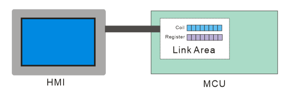
When the operator touches a button on the HMI, the HMI will send a Modbus query addressing the coil or register bound to that button in Comfile Studio. The MCU main program will refer to that coil or register and process the operation accordingly.
To display a value from the MCU in the HMI, the MCU main program will simply have to update the appropriate coil or register, and the HMI will send a Modbus query to read from that location and display the value on the screen.
The global Coil and Register array play a critical role. With the HMI and MCU both sharing access to those arrays, the two act as one cohesive system.