Table of Contents
Input/Output Circuits
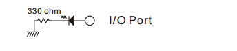
How to connect LEDs
Connect an LED as shown below, and output a logic high to the connected I/O port to turn the LED ON.
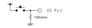
How to connect push buttons
Connect a push button as shown below, and set the connected port's I/O mode to input. When the button is pressed, the Cubloc will read logic high; otherwise it will read logic low.
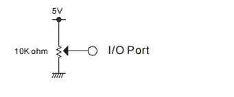
How to connect a potentiometer
Connect the potentiometer as shown below to an A/D I/O port and use the ADIn command to read the position of the potentiometer.
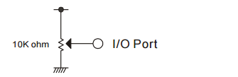
The Cubloc core module uses 5V power. When using a larger voltage, please use an appropriate voltage converter or regulator.
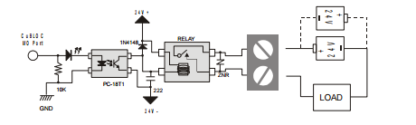
How to Connect an Output Relay
The following diagram shows how to connect an output relay to a Cubloc I/O port. A photocoupler can be used to separate isolate 24V and 5V circuits and protect against noise. Noise coming from 24V circuit will not affect the 5V circuit and vice-versa.
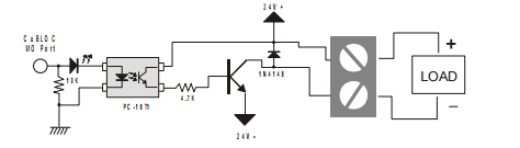
How to Connect an NPN TR Output
This circuit diagram shows an NPN TR photocoupler separating the 5V circuit from the LOAD.
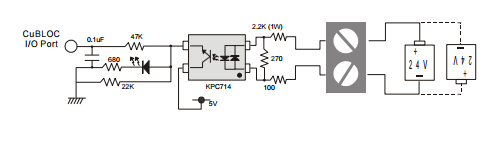
How to Connect a DC24V Input
Use a double polarity photocoupler to convert 24V signals to 5V signals. When input is received, the Cubloc will receive a logic high(5V) signal.
How to connect an AD Input
To connect an AD input to the CB280, the AVDD and AVREF pins must be connected to a 5V source. AVREF is the reference voltage that the ADC uses to do conversions.
If a 5V source is connected to the AVREF pin, input voltages from 0 to 5V will be converted and if a 3V source is connected to the AVREF pin, input voltages from 0 to 3V will be converted.
The CB220’s AVREF are internally connected to 5V. The following is the simplest AD input circuit using a potentiometer. When you turn the knob, the voltage will be converted by the Cubloc ADC to a digital value from 0 to 1023.
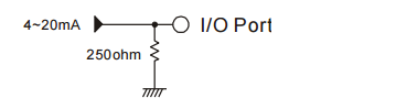
The following illustrates a 4-20mA signal connected to the ADC input port. You can use a 230 Ohm and 20 Ohm resistor in series instead of a 250 Ohm resistor.
For an input voltage from 0 to 10V, use 2 resistors as shown below. This is called a voltage divider.

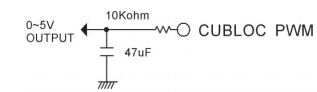
How to use a PWM as Digital-to-Analog converter
The Cubloc has 6 PWM ports. If you use a simple circuit like that shown below, you can make a digital-to-analog converter.