
Table of Contents
About Modbus
Modbus is a protocol developed by Modicon as an interface to their PLCs.
It is usually used with devices like touchscreens, HMI devices, and SCADA software; most of which now support Modbus.
In Modbus, there are master and slave devices. The master sends commands while the slave receives and responds to commands. The slave can only respond to a master; it cannot initiate communication on its own.
Each slave has a unique address called a slave address. The master, using those slave addresses, can talk to one slave at a time. For 1 to 1 connections, RS-232 can be used. For 1 to N connections, RS- 485 can be used.
The master sends messages in units of “frames”. Each frame contains the slave address, command, data, and checksum codes. The slave receives a trame, analyzes it, performs the requested function, and responds. When responding to the master, slaves also respond in frames.
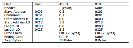
There are two Modbus transmission modes, ASCII and RTU. RTU is binary and can be implemented in fewer bytes than ASCII, making it a little more compact. ASCII uses a Longitudinal Redundancy Check (LRC) for error checking while RTU uses a Cyclic Redundancy Check (CRC).
The table below shows a Modbus frame in both ASCII and RTU:
Cubloc Support
NOTE: Starting with Cubloc Studio v3.3.1, the CB400, CB405 and CB405RT no longer support Modbus ASCII. However, Modbus RTU is still supported, so please use Modbus RTU instead.
Cubloc supports Modbus functions 1,2,3,4,5,6,15, and 16
| Function Code | Function Name |
|---|---|
| 01, 02 | Bit Read |
| 03, 04 | Word Write |
| 05 | 1 Bit Write |
| 06 | 1 Word Write |
| 15 | Multiple Bit Write |
| 16 | Multiple Word Write |
In Modbus, there are addresses that correspond to Cubloc registers. Cubloc’s registers P, M, F, C, T, and D can be accessed using the addresses in the following table:
| Bit Units | Word Units | ||
|---|---|---|---|
| Address | Register | Address | Register |
| 0000H | P | ||
| 1000H | M | ||
| 2000H | Not Used | ||
| 3000H | Not Used | ||
| 4000H | F | ||
| 5000H | T | ||
| 6000H | C | ||
| 7000H | D | ||
| 8000H | WP | ||
| 9000H | WM | ||
| 0A000H | WF | ||
Using Modbus with HMI / SCADA Addresses
The following describes the address mechanism to be used from HMI / SCADA software.
| Data Type | Range |
|---|---|
| Coil | 1–999 |
| Input Status | 10001 – 19999 |
| Input Register | 30001 – 39999 |
| Holding Register | 40001 – 49999 |
To determine the appropriate address to use from HMI / SCADA software, refer to the following table.
| Word Region (Holding/Input Registers) Relevant Function Codes: 3,4,6,16 | |
|---|---|
| Area of the Cubloc to be addressed | Address to be entered in the HMI / SCADA software |
| D area (D0 ~ D511) | 40001 ~ 40512 |
| T area (T0 ~ T255) | 41001 ~ 41256 |
| C area (C 0~ C255) | 42001 ~ 42256 |
| WM area (WM0 ~ WM255) | 43001 ~ 43256 |
| Bit Region (Coil, Input Status) Relevant Function Codes : 1,2,4,15 | |
|---|---|
| Area of the Cubloc to be addressed | Address to be entered in the HMI / SCADA software |
| P area (P0 ~ P127) | 1 ~128 or 10001 ~10128 |
| M area (M0 ~ M2047) | 4097 ~ 6144 or 14097 ~ 16144 |